Why in-field testing an electric motor with a multimeter might not be such a good idea.
We had a call-out to a customer over the bank holiday weekend where they were having trouble with an inverter tripping each time it tried to drive a motor. The information we had from the site engineers was that the motor tested ok and the drive seemed ok, yet it kept tripping.
It turned out that the guys on site had tested the motor’s insulation resistance to earth and that was ok. They’d also tested the winding resistance and all three phases were balanced at 0.1 Ohms.
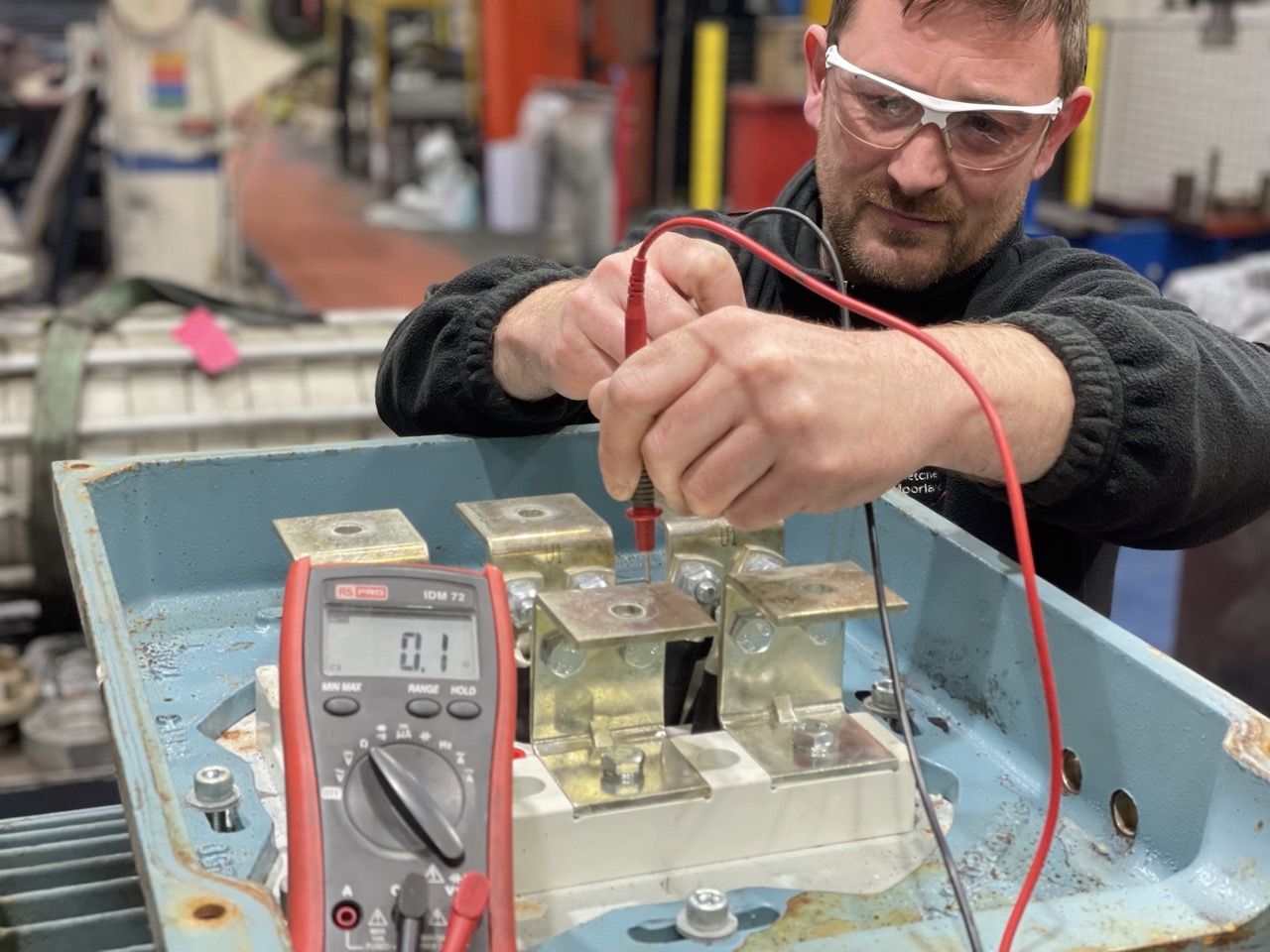
Ok you might think, however that’s where the problem is, they tested a motor of 200kW with a multimeter. I realise that there are many of you probably reading this realising the problem straight away, however these things happen and I’d like to educate those who don’t know.
Multimeters are not accurate enough to do a resistance comparison test on larger electric motors. The larger a motor is the more copper there is inside. The more copper the lower the coil resistance. Think of the wound copper wire as a road, smaller motors often have single wires wound many times, a bit like a winding country road. Larger motors haver many strands wound together in shorter distances, a bit like a many lane race track. Now think of the resistance to current flowing down each coil, you can push more current down the wider shorter coil because it has less resistance. I hope that makes sense, it was how it was taught to me in a GCSE physics lesson many years ago.
Larger motors have coil resistances in milli-Ohms, multimeters simply cannot measure this low resistance and often give a result in the lowest they can. In this example we have recreated what was seen on site with the red multimeter showing 0.1 Ohms. The guys on site saw all readings giving this result and assumed the resistance was balanced and hence the motor was ok.
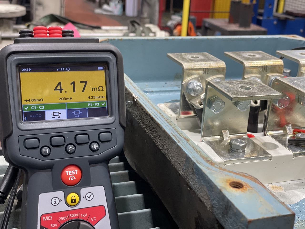
Most electric motor repair companies have much more accurate equipment to assess motor windings such as low range Ohmmeters, Baker winding analysers, Electrom surge testers etc. In this example we have used a Megger MTR105, a great front-line tool to show its low Ohm functionality to show the winding resistances. You can see that one reading, a good phase, at 4.07 milli-Ohms. Another phase, the faulty one, at 21.43 milli-Ohms.

These differences would have never been picked up by a standard multimeter yet the drive tripped because of the current imbalance due to the shorted turns on one of the phases. This motor will now be rewound here.
If you are responsible for front-line testing electric motors on your site I’d suggest, if you don’t already have one, to at least have a low range Ohmmeter. Having one that compares the winding inductance and capacitance is also beneficial. It can save you time in diagnosing faults on your electric motors. Some winding faults are very subtle indeed.
#engineers
#testing
#electricmotors
#electricalengineering
#maintenanceandrepair